
UPDATE 2013-06-01:
While this post still has relevant information, the engineers at BeatBots have created a far more stable firmware. I highly recommend using their MyKeepon firmware, as it fixes a lot of the timing issues the KeepOff firmware had. The MyKeepon firmware is available at:
https://github.com/beatbots/MyKeepon
UPDATE 2011-11-14:
Keepon hacking has made a major step! Thanks to mAngO on the comment thread for my last keepon post, we now know that grounding out the bus during keepon's powerup allows you to act as the master to the bus! There's a Proof of Concept video posted on youtube now.. I'm leaving the rest of this post as it was when I first wrote it for history sake, but the information in it plus knowing that you just need to hold down the I2C lines for a second when the keepon powers up are enough to actually get control going. The reverse engineering document and code in the keepoff repository will be updated to reflect this information.
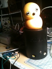
I'm really not sure I've never spent so much time cursing at something so adorable. The past week has been yelling, crying, and generally losing my emotional shit toward a few servos wrapped in a weird, sticky plasticy skin, better known as the MyKeepon Dancing Robot.
How better to atone for my sin of the vivisection of the most adorable christmas toy this year, than writing up what I found. That way, future generations can avoid the pain inflicted on it, and the pain it inflicted on me.
But good lord, it's so fucking CUTE.
Usually I wouldn't write this up until after I had things completely finished, but I gave myself a week deadline for that, and that deadline passed 2 days ago. I'm still in the middle of a few different ideas for reversing it, but those could take a while (stupid real life getting in the way of toy hacking), so I figured I'd dump what information I do have now.
Resources
Before I get into technical descriptions, the current resources available for updates on keepon hacking are:
- The Keepoff Project Github Site
- Keepon Reverse Engineering Doc
- My twitter account for real time updates
- My flickr account, for pictures when I remember to upload them
Default Interfaces (i.e. What It's Supposed to Do)
The MyKeepon robot isn't the most complicated toy in the world. The main selling points of the toy are that it's cute, it's interactive, it can dance to your music, and it's cute.
To establish the interactive cuteness, the following interfaces are available to users:
- 2 Front Buttons, for switching between "Touch" and "Music" mode
- 5 Body Buttons, inside the skin of the keepon. 4 around the sides, one on the top of the head.
- A Microphone in the nose
There's 4 degrees of freedom in movement for the MyKeepon (X-Axis horizontal, Y-Axis up, Z-axis thru):
- Base rotation, that rotates the whole bot around the Y-Axis.
- X-Axis bend, for bending the head/body left/right
- Z-Axis bend, for bending the head/body forward/back
- Y-Axis compression, for 'squatting' (action when top of head button is tapped)
A speaker is also available for playing sounds. There is no volume knob, sounds are always on, and always loud. The secondary market for keepons with volume knobs installed is going to be killer.
Keepon States
MyKeepon has 3 states when powered on:
- Touch - Pays attention to buttons, looks around
- Music - Listens for music, or dances to rhythm tapped out using head button
- Sleep - Processor(s) in low power state, can be brought out of sleep by hitting music button or tapping head, which causes reset line to be pulled.
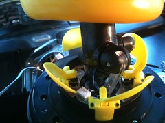
Mechanisms and Power
Keepon runs on a 12v supply, using either 8AA batteries in what has to be the worst enclosure I've ever had the displeasure of jamming batteries into, or using a 12v plug, not sold with the device (though they give a TON of info about the plug sizes needed in the manual, a surprising, rarely seen bit of information). The 12V runs to the motors, and is stepped down to 3.3v for the internal circuit.
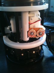
Each of the motors has an encoding mechanism on it, but I haven't really done much work figuring out exactly what it is yet. I believe the largest motor for turning the base is a regular gear motor (see encoding conjecture below), but the bend motors may be small servos.
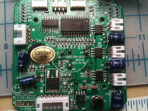
On the circuit board, there are 3 pins (see picture below) that come in contact with this piece that's mounted on top of the battery pack. It's used to recenter the bot on boot, as no state may be available for motors to know their postion at time of last power off. The bot being centered is the only position where the middle pin won't have an electrical contact with one of the outer pins on the circuit board. This accounts for part of the "startup time" mentioned in the keepon manual.
Circuits and Chips
There's one main circuit board in the MyKeepon, with 2 very odd processors.
The microprocessors are
- Padauk P234CS20 (P234 chip in a SOP20 package)
- Padauk P232CS14 (P232 chip in a SOP14 package)
Their data sheets describe them as FPPAs, or "Field Programmable Processor Arrays". I have no idea how this makes them special. They're dual core, hence the "processor array", but other than that, they look like they're One Time Programmable, hence the Field Programmable part being... questionable at best. Also, as marcan found, they tend to straight up lift figures and paragraphs from the PIC datasheets.
The two processors talk to each other via I2C. The PS232 deals with sound and encoders and is the slave node on the I2C bus, while the PS234 handles driving the h-bridges, main processing (including handling button presses), and is the master node on the I2C bus. There's more info on this communication in the next section.
There's 3 H-Bridges, running to the motors listed earlier.
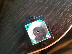
I2C Bus and Protocol
The MyKeepon developers have been nice enough to provide pads to access the I2C bus between the processors. Looking at the board with the solder mask facing up, it's on the lower left hand side of the board, marked with a gigantic smilie face. So they were damn well aware of what they were doing.
For those not familiar with the I2C Bus, there's a good tutorial at http://www.i2c-bus.org/.
The pads exist on the bus between the processors, meaning that you can see how the master node addresses the slave node. I2C addresses are for "devices", and there can be up to 127 devices on the bus, that can be written to/read from. As of this writing, only 2 devices have been found:
- 0x52 - Sound
- 0x55 - Motors
To trigger a sound, an message is written by the master node to the bus in the format "0x01 0xWW", where WW is the index of a sound. The following indexes are known so far (though more sounds are certainly available, they just haven't been mapped yet):
Motor messages are 3 bytes, of the format "0xUU 0xWW 0xVV", where:
- 0xUU: Motor Index
- 0xWW: Motor Position?
- 0xVV: Unknown
To retreive information about the motors, a read request for 12 bytes is sent to device 0x55. In normal communications between the processors, this request is sent every ~15ms by the master node. Format of the returned information is currenly unknown.
Information about button presses (either body or base buttons) and input from the microphone do not seem to be relayed across the I2C bus.
Accessing the I2C Bus
Since the protocol of the I2C bus is (mostly) known, the problem becomes talking to the devices on the bus. The tap exists in between the chips, and the master node does not seem to have the capabilities to work on a multimaster bus (not to mention, the default animations being timing based means we can't stop moves we don't want from being sent). When the device is asleep, the data and clock lines are pulled to ground, meaning we can't actually communicate to any of the other devices.
The only current solution seems to be to lift the I2C pins on one of the chips. This seems like the wrong thing to do, since the pads are obviously available and there's a smilie face above them, letting on that there's some way to easily access the hardware on the board.
Simple Modifications

I've only made a couple of small modications so far. The first is running a wire from the I2C pads out of the bot. I dremeled a small hole in the back near the plug outlet, and made sure the wire had a LOT of play inside the bot, since turning pulls it around inside.
The second is putting a switch in between the speaker wires. This allows for the sound to be turned off, which is a huge blessing when you're just trying to watch the bus. A rheostat could also be installed to turn the volume down. There's a good amount of room for installation of the rheostat inside the device.
What's Left to Do
The protocol is known for the motors and sound banks, outside of what the 12 byte return from the motor device is. I've actually got a board where I've lifted the I2C pins on the slave processor, and am going to see whether I can communicate directly with it. Everything I'm using that talks I2C doesn't deal with arbitration of a multi-master bus, so it could very well be that the master node on-board will arbitrate correctly if another node interrupts, but I haven't figured out whether or not that is true yet. It really does seem like there should be an easier, non-pin-removing way to speak to the chips on the bus, and I'm really hoping no one follows my lead on pin lifting before we figure it out.
However, once all that's done, we should have a completely USB controllable keepon, which I then have all sorts of ideas for, except NO NOT THAT you pervert.